
Conventional installation
High imported material dependency
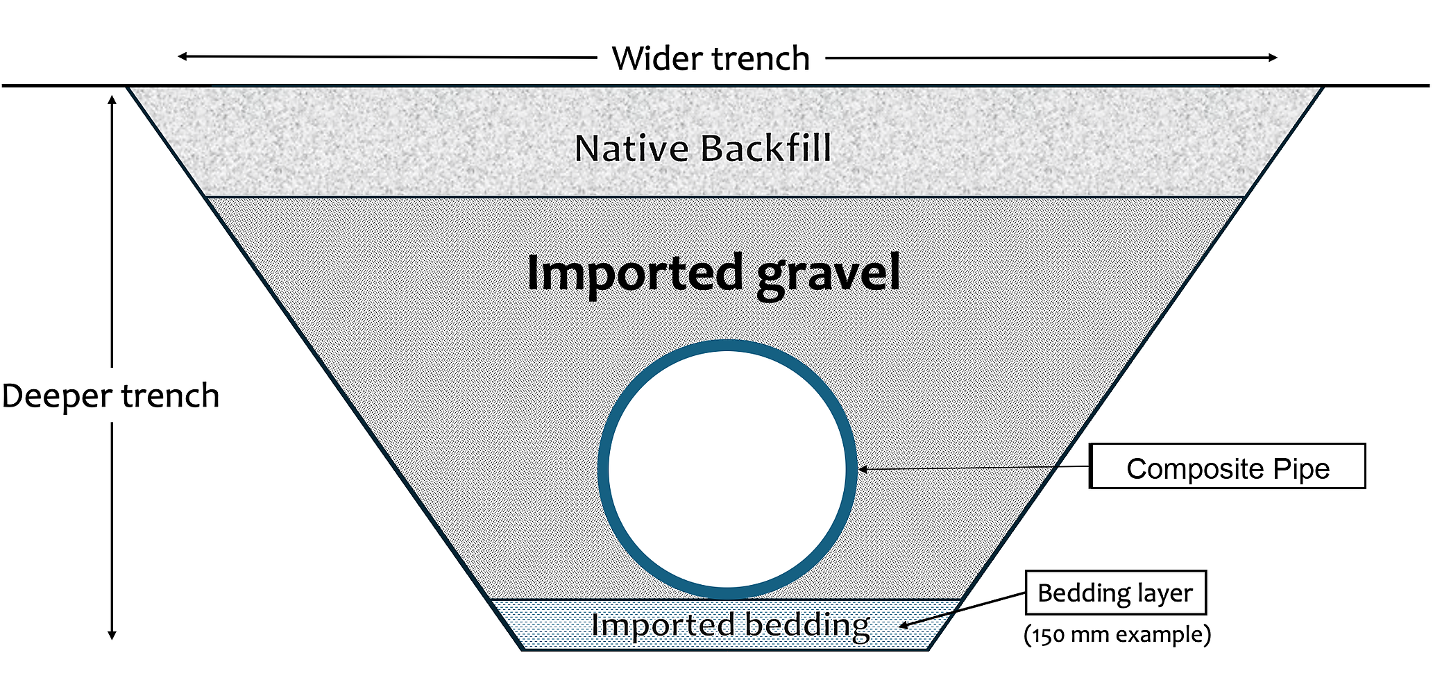
Method
HydroFoamer uses engineered sprayed PU foam, installation control and as-built evidence to do the same buried pipeline job with less imported material, fewer hidden assumptions and more visible control.
Engineering comparison
Conventional buried composite pipe installation relies heavily on imported bedding and embedment material. HydroFoamer replaces much of that dependency with engineered sprayed PU foam keyhole support geometry and native backfill.
High imported material dependency
Engineered keyhole support geometry
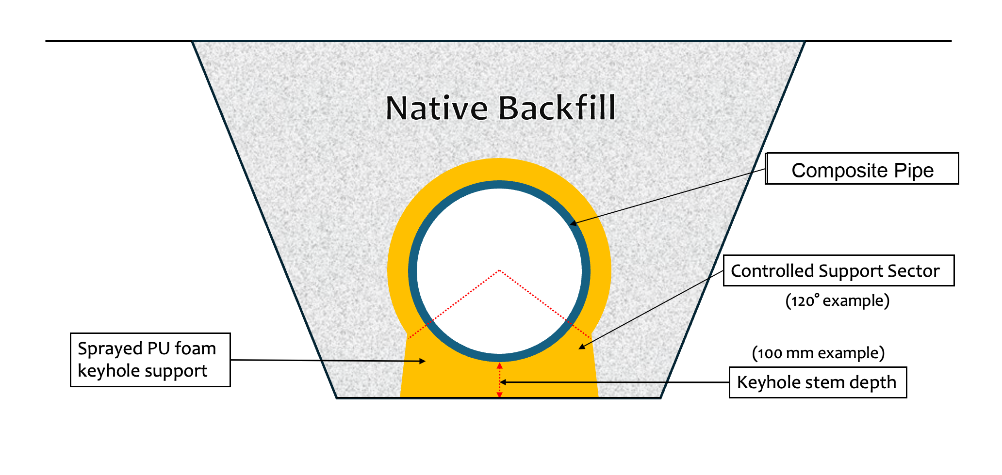
Illustrative sections based on HydroFoamer engineering principles and Eikeelva / HYWER geometry. Final geometry is project-specific and depends on pipe diameter, cover, soil conditions and required support behaviour.
Video
The 2026 video shows the controlled application of sprayed PU foam around a composite pipe section, illustrating the support geometry and practical execution logic behind the HydroFoamer method.
The problem
Traditional buried pipeline installation depends on trench geometry, imported bedding, compaction, access, workmanship and inspection quality. The work is heavy and much of the proof comes late. Once the trench is backfilled, the real installed condition is difficult to verify directly.
The method
HydroFoamer applies structural PU foam around the pipe in a controlled keyhole support geometry. The method provides support and restraint while allowing native backfill to replace much of the imported bedding and embedment material normally required. The method moves value from bulk handling into designed support and measured control.
Field workflow
The sequence is designed so the pipe is positioned, checked, supported, verified and handed over with records. The buried asset should not become unknowable the moment backfill is placed.
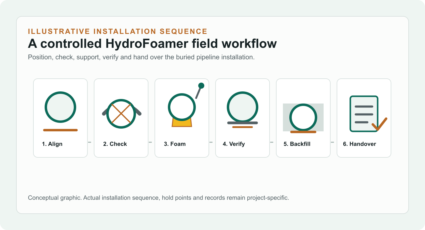
Confirm trench context, working access, pipe specification and target alignment before installation begins.
Position the composite pipe section according to the installation plan and project tolerances.
Check pipe position, angular alignment, coupling deflection and geometry before support is locked in.
Apply structural PU foam to create the defined keyhole support and restraint geometry.
Record measured installation data and check that the installed condition aligns with the project method.
Place native backfill where the design allows, reducing dependency on selected imported aggregate.
Carry installation records into the as-built package for technical review, asset handover and future understanding.
The practical test is simple: before the pipe disappears, the team should know what has been installed, what has been measured and what assumptions remain.
Pipe location and alignment are checked against the installation plan before support is locked in.
Support sector, keyhole depth, pipe diameter and cover assumptions stay tied to the project method.
Movement, settlement and coupling deflection are treated as installation-control questions, not only post-event concerns.
Imported aggregate, native backfill, foam volume and spoil handling can be recorded as project quantities.
QA checks can be attached to the sequence: place, measure, support, verify, backfill and hand over.
The as-built record should help the owner understand the buried asset, not simply close the construction file.
HydroFoamer is not foam instead of gravel. It is a controlled restrained installation method built around support geometry, measurement and evidence.
A defined support sector and minimum keyhole depth provide controlled support and restraint around the pipe.
The method is focused on restrained buried pipelines where movement control, bends and coupling behaviour are important.
Pipe alignment and geometry are checked as part of the installation sequence, not only after the fact.
Measured records connect field checks, installation state, QA/QC and handover evidence.
Native backfill can replace much of the imported bedding and embedment material where project design allows.
The near-term focus is composite pipe systems; broader pipe applications require qualification.
PGMS makes control practical. It supports standalone alignment checks, integration with Leica / total station survey workflows, and handover into BIM and digital twin environments.
PGMS can be used directly in the trench to check pipe alignment, angular position, coupling deflection and installation geometry before and during foam application.
PGMS data can connect with Leica / total station survey workflows to link pipe geometry, measured position and construction control.
Installation data can feed into the BIM and digital twin layer, creating a verified as-built record of the buried pipeline installation.
Bring the pipe system, route constraints and evidence requirements. The useful question is whether this installation method changes the project, not whether foam can be sprayed in a trench.